The Realization: Setting the control points
I assume, you are already familiar with the process of
setting normal control points: One marks the same image feature in two
(overlapping) images. The optimizer will then try to reduce the sum of
control point distances until this sum is as small as possible.
Setting a line is a little different: You don't use two overlapping
images, you use the same image. And you don't mark the same image feature,
but you set the control point along a straight (vertical) line.
Unfortunately, this vertical line will only rotate
the image, it won't align this image vertically. For this reason, we have
to assign more vertical lines - best: one in every source image. For
mathematical/geometrical reasons, this will not only rotate but also move
the image into the correct vertical position - setting the horizon at the
correct level.
We will now do this with a practical example. Like always,
you can download the source images here. If you
have no practical experience in creating a 360-degree panorama, i suggest
reading this article first.
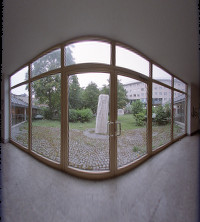
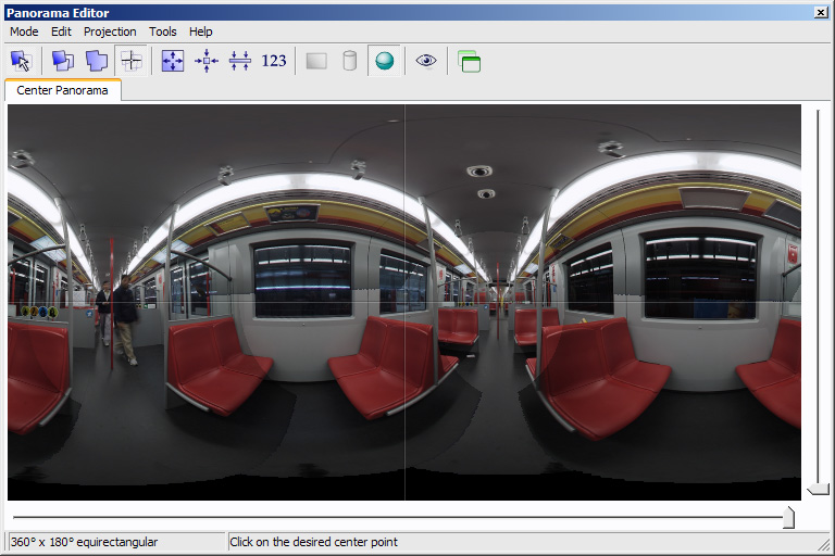
Here, we will continue at the point, where the source images are already
loaded, the normal/standard control points set and optimized:
(In this example, i've enhanced the horizon mis-alignment a little -
meanwhile PTGui is pretty good in automatic alignment...)
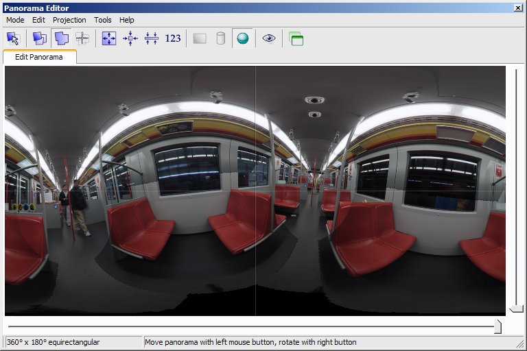
Before we start setting the vertical ("t1) control points,
i want to point out a specific characteristic of this particular panorama.
Although it may not be noticeable - not all verticals are really
verticals. This is because the endwalls of the metro waggon are in reality
slightly tilted. Though - even slightly tilted lines are in practice
better than no verticals at all.
I like to compare the behaviour of control points with
a "lever force". When optimizing, all control points will correlate in
a way that the sum of control point errors will be as low as possible.
This simple rule can be used to priorize the vertical control points:
If you are unsure if a line is really vertical, you can use only a
small section of your vertical line. If you are pretty sure: use a
larger section of your vertical line.
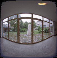
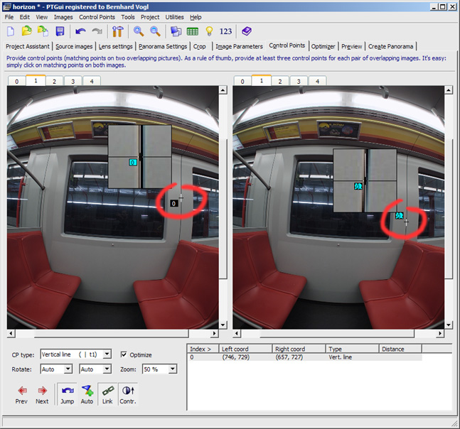
We will now begin to set the first vertical control point:
Switch to the "control point"-tab and select the same source image in both
windows. You will notice that PTGui will automaticalls set the type to
"t1" (vertical line):
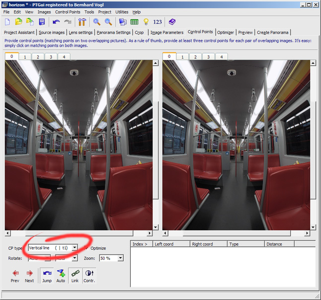
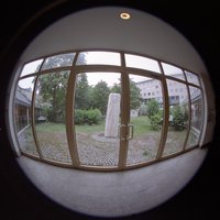
You can see a grab pole in the middle of the picture. We
can safely assume the this pole is built as an exact vertical. So we can
use the complete pole for assigning the control point:
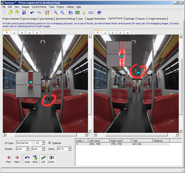
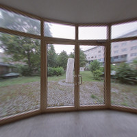
We are now ready with the first picture. Click on the red
"Next"-Arrow to switch to the next source image.
Here we have the problem that we can't be sure that the lines are really
vertical, but we can assume that they are approximately vertical. So we
limit the control point to a smaller section:
You may argue that this doesn't seem to be very exact. Basically you are
right, but this method is still more exact than aligning the panorama by
hand and it also has the advantage to be repeat- and correctable as often
as you want.
The Finale: Optimizing and analyzing the optimizer
result:
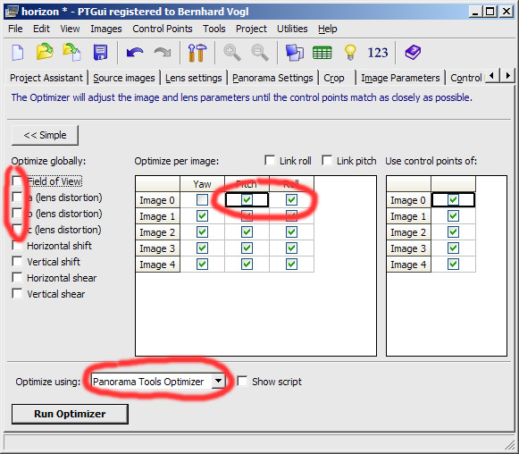
First of all we have to allow free movement and rotation
of all images. We will only prohibit the movement of an anchor image in
X-direction. For not falsifying the result, we will deactivate all lens
optimizations.
Furthermore, we have to use the "Panorama Tools Optimizer" instead of
PTGui's optimizer.
In the following image, all needed modifications are marked red:
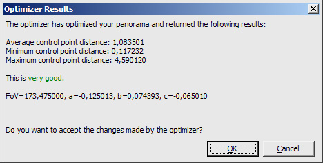
Now we can run the Optimizer and hopefully, the result
will be good:
If you notice a degradation of your Optimizer result,
you can use the "Control Point Table" to find the problem:
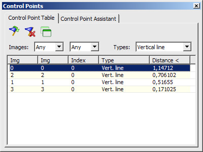
You can see that the distances of the vertical control points only
denote their deviation from a perfect vertical - not their distance from
each other (as normal control points would do).
In our case, we already have a good result. The control points show only
low distances.